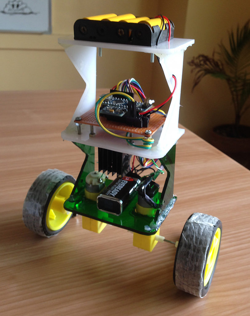
DIY Diy Lab Circuit Diagram This is a relatively simple, visually effective balancing robot project that only requires four components to make. Detailed video, instructions, schematic, and code at: Arduino two weel self Balancing Robot

In this tutorial, we will build a self-balancing robot from scratch, step-by-step. The "brain" of the robot will be based on Arduino, a popular microcontroller (i.e. mini computer) used for robotics projects.

Arduino two weel self Balancing Robot Circuit Diagram
In this instructable, I'll show you how to build a small self-balancing robot that can move around avoiding obstacles. This is a tiny robot measuring 4 inches wide and 4 inches tall and is based on the Arduino Pro Mini development board and the MPU6050 accelerometer-gyroscope module. In my first design, I used a single 5V boost regulator to

JLCPCB Prototype for $2(Any Color): https://jlcpcb.comHello friends this post is about DIY self balancing robot in this post I'll show how you can build your
Balancing Robot : 10 Steps (with Pictures) Circuit Diagram
In this instructable, I will show you how to build Self Balancing Robot use ESP32 Wifi. Let's get started! This self balancing robot is based on: B-Robot EVO 2.0 by JJRobots; B-Robot ESP32; In order to create this project, you must purchase a prototype PCB from PCBWAY. Ordering is quite simple and for only $5, you will receive 10 Pcs of In this way our robot assembly is completed. Now we can move towards the programming of self balancing robot. Programming. Download balancingwii. To start programming arduino first we need to download a firmware for balancing robot called balancingwii. this firmware is based on Multiwii firmware used for quad-copter and multi-rotor flying drones. you can learn here more about Multiwii. 1. The physical structure of the robot is modified, so that the robot is much more robust and easier to control. The very early version is shown in the first picture, while the current version (2.0) is shown in the second picture. 2. An illustration of torque equilibrium of the robot is added. 3. A new program is written for PID tuning.
